EtherCAT Master Stack demo on TI AM64x (TI TMDS64EVM board)
Architecture and platform integration
This diagram illustrates the integration of the icECAT EtherCAT Master Stack on the TI AM64x as supported by the demo software.

The icECAT EtherCAT Master Stack runs on an R5F core based on FreeRTOS.
It interfaces with the TI Enet LLD via the icNET Optimized Link Layer driver.
Ethernet communication is supported at the ICSSG1 ports, utilizing TI’s Dual-MAC ICSSG firmware.
The ENI (EtherCAT Network Information) is stored in XML format on the SD card and parsed at runtime.
The built-in icECAT EtherCAT Configuration Library allows online configuration, based on ESI information, either provided in an ESI repository on the SD card or dynamically retrieved from the SubDevices’ SII (Slave Information Interface).
The icECAT Master Monitor is linked to the MainDevice application and accessible via UART over a serial terminal.
The MainDevice application is built on the TI MCU+ SDK. The board boots with help of the SBL bootloader.
Additional features in the release version:
icNET Optimized Link Layer driver supporting the ICSSG0, ICSSG1, and CPSW3G Ethernet interface on AM64x/AM243x.
ENI can be linked static to the MainDevice application
Integrated LWIP stack for remote tooling via TCP/IP: * icECAT EtherCAT Master Monitor * icECAT EtherCAT Configuration Tool
EtherCAT features, disabled for the demo:
Hot-Connect
EoE
FoE
Cable Redundancy
SDO Info Service
Support for read and write of Explicit Device Identification
Mailbox Gateway and Master object dictionary
Prerequisites
To run the icECAT EtherCAT Master Stack demo, you will need:
A Texas Instruments evaluation board for TI Sitara AM64x (TMDS64EVM) or TI Sitara AM243x (TMDS243EVM) with a power supply. The binary demo software supports both boards.
A micro SD card
A micro USB cable
An Ethernet cable
One or more EtherCAT SubDevices, optionally with ESI files
icECAT EtherCAT Master demo software for TI Sitara AM64x on TMDS64EVM
Demo setup
Hardware setup
The following figure illustrates the hardware setup.

Follow these steps for the hardware setup:
Configure the boot mode switches on the EVM for SD BOOT MODE:
SW2
SW3
BOOTMODE [0:7]
BOOTMODE [8:15]
1100 0011
0110 1100
Connect the upper port of the ICSSG PHY network socket to your EtherCAT network.
Connect J26 (USB UART) to your PC using a micro USB cable for the serial terminal.
On your PC, four serial COM ports will appear. To find the correct COM port on Windows:
Open the Windows Device Manager and check for four USB Serial Port devices from FTDI.
Use the first detected port for the UART terminal connection.
Open a serial terminal (e.g. PuTTY or the terminal view in TI CCS) on this COM port with the settings:
115200 baud, 8 data bits, no parity, 1 stop bitFor more details, see Setup the UART terminal
Connect the 12V power supply to the EVM.
Software setup
Ensure the SD card is bootable. The first partition must therefore be FAT-formatted and marked as ACTIVE. Detailed guide: Booting the EVM from SD card
Copy the following binaries from the icECAT Master Demo software package (
sdcardfolder) to the FAT partition of the SD card:tiboot3.binappOptional: If you already have an ENI file for your EtherCAT network, copy it to the SD card named as
eni.xml.Optional: If you have ESI files for your EtherCAT SubDevices, create an
esirepofolder on the SD card and store the ESI XML files there.
Insert the SD card into the EVM.
Starting the demo
Power on the EVM. The terminal should display:
DMSC Firmware Version 9.2.7--v09.02.07 (Kool Koala)
DMSC Firmware revision 0x9
DMSC ABI revision 3.1
<<...>>
Image loading done, switching to application ...
Starting EtherCAT MainDevice Demo Application ...
Wait until an SD card is inserted ...
Enabling clocks!
Mdio_open:294
EnetPhy_bindDriver:1828
PHY 3 is alive
PHY 15 is alive
Enabling clocks!
Mdio_open:294
EnetPhy_bindDriver:1828
PHY 3 is alive
PHY 15 is alive
                        __            ________   ______    ______   ________
      ....... <<<<<<<  /  |          /        | /      \  /      \ /        |
    : ------- <<<<<    ##/   _______ ########/ /######  |/######  |########/
  : / ....... <<<      /  | /       |## |__    ## |  ##/ ## |__## |   ## |
 : / :....... <<<<<    ## |/#######/ ##    |   ## |      ##    ## |   ## |
: | ::        <<<<<<<  ## |## |      #####/    ## |   __ ######## |   ## |
: | ::        :: | :   ## |## \_____ ## |_____ ## \__/  |## |  ## |   ## |   __
 : \ ::......:: / :    ## |##       |##       |##    ##/ ## |  ## |   ## |  /  |
  : \ :......: / :     ##/  #######/ ########/  ######/  ##/   ##/    ##/   ##/
    : -------- :
      ........         EtherCAT Master Stack for Embedded Systems
                       Limited Demo Version >...<


  Copyright (c) by IBV - Echtzeit- und Embedded GmbH & Co. KG
  https://www.ibv-augsburg.de/icecat

  This is a demo application for the

    icECAT EtherCAT Master Stack for Embedded Systems

  The EtherCAT MainDevice software is designed for use on
  microcontrollers, microprocessors and PC systems
    > Optimal performance
    > Small footprint
    > Project based source code license, royalty free

> Press ENTER to continue...
After initialization, the system prompts for setting up the configuration:
Network setup: Choose between a physical EtherCAT network or the icECAT EtherCAT Network Simulation library.
EtherCAT network configuration: Scan the network or use the pre-configured eni.xml.
Cycle time configuration
Output options: icECAT Master Monitor, performance monitor, or extended logging
For an initial test, select 0 for all options.
The MainDevice demo then starts. The terminal should display:
=== init EtherCAT master
=== create link layer driver  options ><)

-[COPYRIGHT]-------------------------------------------------------------------
   (C) IBV - Echtzeit- und Embedded GmbH & Co. KG
   https://www.ibv-augsburg.de/icecat
-[PRODUCT]---------------------------------------------------------------------
   icECAT - EtherCAT Master Stack
   Version:               1.12...
-[SYSTEM]----------------------------------------------------------------------
   Operating System:      ...
   Target Architecture:   ...
   Link Layer Driver[0]:  ...
-[DEMO-VERSION]----------------------------------------------------------------
!! USE ONLY FOR DEMONSTRATION PURPOSES                                       !!
!! FOR USE IN PRODUCTION SYSTEMS, A COMMERCIAL LICENSE IS NECESSARY.         !!
-------------------------------------------------------------------------------

=== create linked monitor
=== create icECAT Configuration Library instance

-[COPYRIGHT]-------------------------------------------------------------------
   (C) IBV - Echtzeit- und Embedded GmbH & Co. KG
   https://www.ibv-augsburg.de/icecat
-[PRODUCT]---------------------------------------------------------------------
   icECAT - EtherCAT Configuration Library/Tool
   Version:               1.16...
-[SYSTEM]----------------------------------------------------------------------
   Operating System:      ...
   Target Architecture:   ...
-[DEMO-VERSION]----------------------------------------------------------------
!! USE ONLY FOR DEMONSTRATION PURPOSES                                       !!
!! FOR USE IN PRODUCTION SYSTEMS, A COMMERCIAL LICENSE IS NECESSARY.         !!
-------------------------------------------------------------------------------

Open ESI repository:/sd0/esirepo repoindex:/sd0/repoindex.ini
=== run main loop
=== activate master
=== Request startup state:8
Afterwards the MainDevice tries to setup the network to OPERATIONAL state. If successful, the ACTIVITY LED on your EtherCAT SubDevice(s) should blink and the RUN LED should be on. If the setup fails, restart the demo and enable extended logging for troubleshooting.
Furthermore, the icECAT Master monitor is shown on top of the log output in blue color. The selectable screens and their hotkeys are listed.
EtherCAT MainDevice demo application
The MainDevice demo application can be used to control the EtherCAT MainDevice stack with help of the icECAT Master Monitor tool. In the release version, a programming API is provided to control the network, access the process data, etc.
EtherCAT network configuration
If no ENI (EtherCAT Network Information) file is provided, the application automatically scans the network for connected EtherCAT SubDevices. It retrieves the ESI (EtherCAT Slave Information) data from the SII (SubDevice Information Interface) repository or, if unavailable, reads the SII data from the SubDevice’s EEPROM.
An ENI is generated using the integrated icECAT Configuration Library, stored in RAM and linked to the MainDevice stack. This configuration defines the network topology, the initialization for the process variables, and the structure of the cyclic frames.
Here is a sample of the related output:
Start network scan...
Network scan done. Found 3 devices.
List of devices found in network scan:
   dev#-1 prod=0x00000000 rev=0x00000000 <icECAT EVAL Master       > type=
   dev#00 prod=0x044C2C52 rev=0x00120000 <EVAL Slave 01 ()         > type=
   dev#01 prod=0x07113052 rev=0x00110000 <EVAL Slave 02 ()         > type=
   dev#02 prod=0x0AF93052 rev=0x00120000 <EVAL Slave 03 ()         > type=
ESI not available for all devices => use online SII as fallback
Start SII reading ...
SII read done: (4)
Generate basic ENI
lib-ecatmcfg EVENT >00h00m01.176 INFO  EMCFG_EVTC_ENI_PROCESS_START: Processing ENI ... <
lib-ecatmcfg EVENT >00h00m01.184 INFO  EMCFG_EVTC_ENI_PROCESS_END: Processing ENI finished. <
List of devices found in network scan:
   dev#-1 prod=0x00000000 rev=0x00000000 <icECAT EVAL Master       > type=
   dev#00 prod=0x044C2C52 rev=0x00120000 <EVAL Slave 01 (EK1100)   > type=EK1100
   dev#01 prod=0x07113052 rev=0x00110000 <EVAL Slave 02 (EL1809)   > type=EL1809
   dev#02 prod=0x0AF93052 rev=0x00120000 <EVAL Slave 03 (EL2809)   > type=EL2809
Request linking of network scan ENI
use ENI from network scan
create cyclic task (cycidx=0; prio=1; cyctime:1000us)
=== run cyclic task (cycidx=0, cyctime:1000 us)
=== activate master
=== Request startup state:8
EtherCAT Network Configuration with an external configuration tool
As an alternative to an automatic online configuration, an ENI can be generated
with an external tool and provided to the stack as XML file (eni.xml).
IBV provides the icECAT EtherCAT Configuration Library with a GUI tool for generating a network configuration. Ask IBV for an evaluation version. As alternative, you could use Beckhoff TwinCAT 3 to generate an ENI.
EtherCAT network state
Enter the EtherCAT network screen by pressing SHIFT+N in the monitor.

In this screen, the states of the MainDevice and of all SubDevices are shown. Select the device with the UP/DOWN keys and start a state transition with one of the keys i / b / p / s / o as indicated on the bottom status line.
If the SubDevice reports a problem, the AL_STATUS code is shown in column ALCODE.
Loading of an ENI file can be initiated by pressing “l” (small “L”) . By typing “scan” as ENI file name, an online network scan is triggered.
PDO access (process variables)
Enter the screen with I/O variables (PDOs) by pressing SHIFT+I in the monitor.

In this screen, select the process variables with the UP/DOWN keys. The current value is shown on the right side.
If an output value is selected, it can be modified by pressing ENTER and by
entering the new value as decimal number or as hexadecimal number with 0x
as prefix.
When working with a CiA402 drive, the CiA402 state machine can be controlled by writing the CONTROL WORD and inspecting the STATUS WORD.
SDO upload and download
A SubDevice related screen can be entered by selecting the SubDevice in the network screen and pressing ENTER. The LEFT / RIGHT keys select the previous or the next SubDevice.

If the selected SubDevice supports the CoE mailbox protocol
you can read (=upload) SDOs by pressing “u” and entering the SDO index and subindex,
e.g. 0x1008:0
If the SDO is writable, you can press “d” and enter the SDO index and subindex. Afterwards the value can be entered as hex bytes in little endian format.
ESC register access
The registers of the ESC (EtherCAT SubDevice Controller) of a SubDevice can be inspected by selecting the device the network screen and pressing SHIFT+R.

Scroll in the ESC register list with the UP/DOWN keys. By pressing ENTER, you can enter a new value to be written to the register. Example: Writing to the AL Control register (0x0120) will modify the application layer state of a SubDevice.
Diagnostic information
A screen with MainDevice related statistics and diagnostic information can be entered by pressing SHIFT+M.

In the middle, of the screen DC (Distributed Clocks) timing statistics are shown. For a reliable operation in DC mode, the counter missed shall be 0.
In the lower part, statistic counters of the Ethernet link layer driver are shown.
Performance monitor
The MainDevice demo application contains a built-in performance monitor. It can be activated when starting the demo. The performance monitor shows live values as well as min/max values of the EtherCAT timing as soon as the MainDevice enters the OPERATIONAL state:
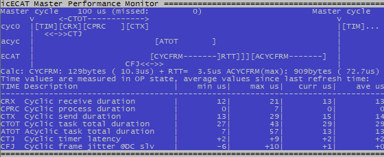
Performance values for the platform TI Sitara AM64x on TMDS64EVM
The values in the table at the bottom of the screen are:
CRX: Time for receiving (getting and evaluating) the response frame from the last cycle
CPRC: Time for processing the data on application level (0 in demo application)
CTX: Time for transmitting (passing the frame to the Ethernet controller for transmission)
CTOT: Total operation time in cyclic task for one cycle
ATOT: Total operation time in acyclic task for one cycle
CTJ: Latency/jitter of the cyclic timer. This value is related to the hardware / RTOS performance and results in a frame jitter (CFJ) in the same range.
CFJ: Jitter of the cyclic frame measured with the clock of the DC reference slave. If this min/max value is out of the bandwidth shown in the Performance Monitor screen, then the SubDevices did not get updated information for the next cycle in time.
EtherCAT network simulation
The MainDevice demo application contains the icECAT EtherCAT Network Simulation Library. This component simulates an EtherCAT network to a certain extent that the MainDevice stack is able to setup the network. On API level, the behavior for input/output variables could be simulated in a custom application. This could be used to develop a MainDevice control application without requiring a physical network of SubDevices. The simulation of I/O values is not supported by this demo application.
The built-in icECAT EtherCAT Network Simulation Libray can be used if no physical EtherCAT SubDevices are available. This requires an ENI file to define the simulated network topology. Select the network simulation option in the setup screen when starting the demo.
Note
Not all features of the icECAT EtherCAT Master Stack are supported by the network simulation.
Full-featured software
A full-featured evaluation version of the icECAT EtherCAT Master Stack and the icECAT EtherCAT Configuration Library is available upon request.